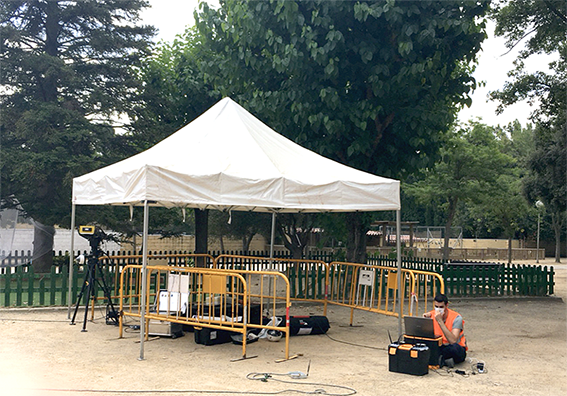
From 27th to 31st July, SIART and IDSGEORADAR were at Sant Cugat pilot for structural monitoring, during the same week drilling works started. The goal was to perform structural monitoring before and during drilling, and see any impact in the school buildings.
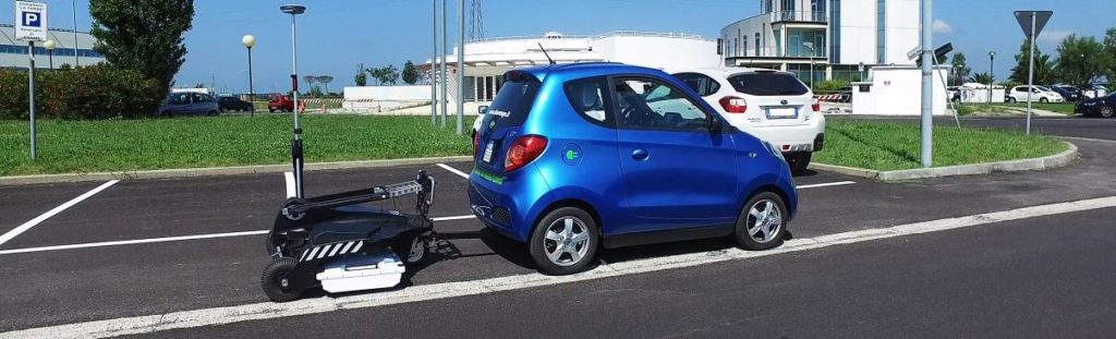
IDSGEORADAR installed a Hydra-G system which monitored real-time measurements of sub-millimetric displacements in the administrative building and in the primary school. This system provides the high-accuracy and resolution radar technology. The system was accompanied by an optical and infrared HD camera providing real- time visual inspection of monitored area, draping radar data on a 3D model of the scene created using the radar system.
On the other hand, SIART installed several accelerometers in both buildings, administrative and primary school, to monitor vibrations before and during the first drilling carried out on 31st July. The goal of monitoring before drilling works is to know the building frequency, and see, once the drilling starts, if it has changed due to the vibrations propagation throughout the terrain. Once data has been captured, SIART will analyze them and present some results.
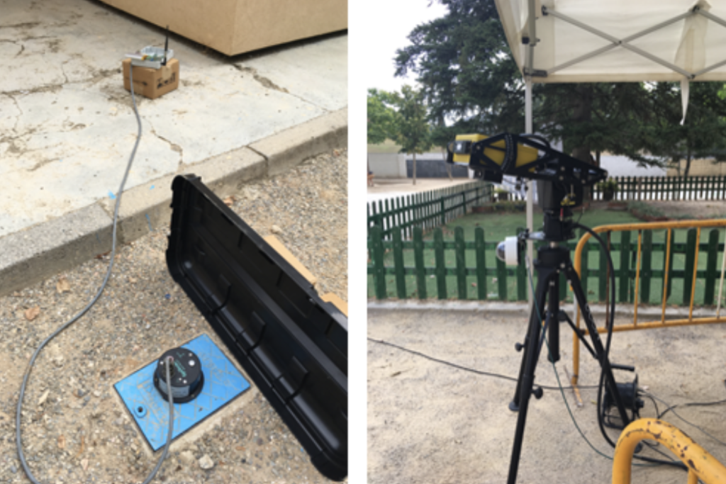
On the left: one of the accelerometers installed by SIART; On the right: Hydra-G system and camera installed by IDSGEORADAR.
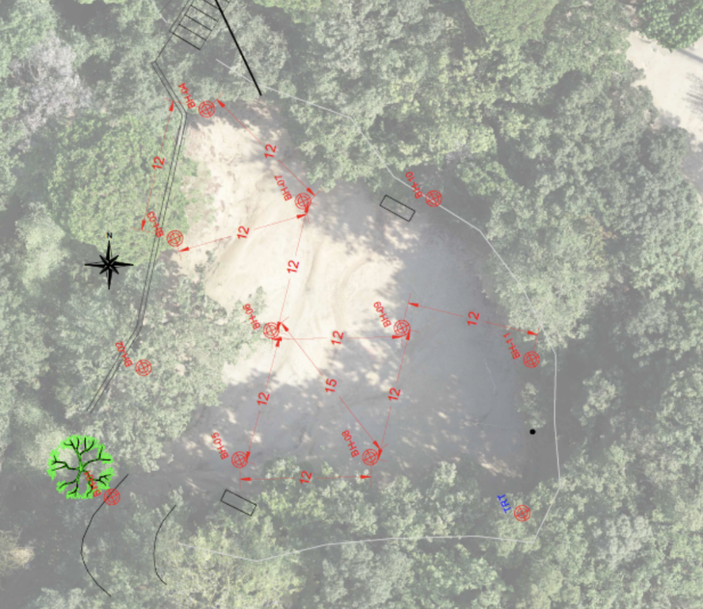
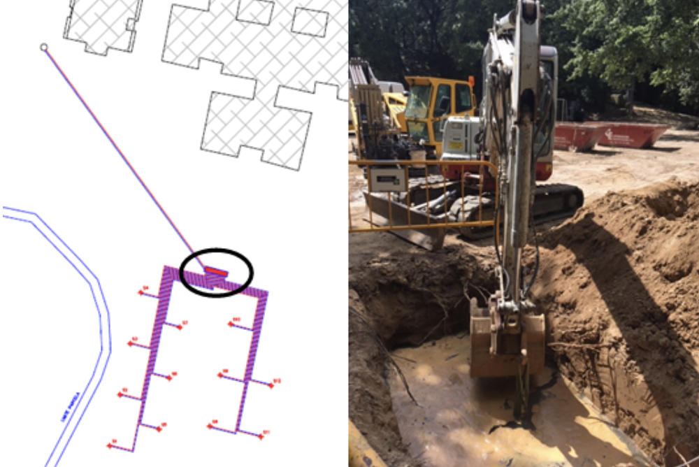
On 31st July, Catalana De Perforacions (CDP) started the drilling works at the Sant Cugat demo site. The design of the geothermal field consists of 12 boreholes up to 120m deep and one Horizontal Directional Drilling (HDD).
Image 1: location of the 12 boreholes.
While drilling the first well, some problems with the ground material, mainly clays, and the groundwater level at depths beyond around 60 meters were faced. The borehole heat exchangers are double U PERC 100 SDR 11 PN16, with a diameter of 32mm.
On the other hand, on 3rd of August, the works related to the horizontal connection between the collection chamber and the plant room where the Ground Source Heat Pump (GSHP) will be installed, also started.
These works, including the geothermal field and the horizontal connection between the chamber and the plant room, should be completed on 31st August according to schedule.
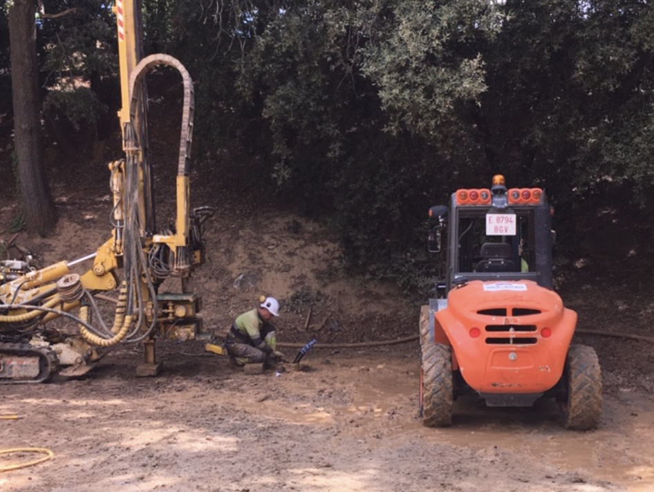
Image 2: the second borehole drilled
Image 3: excavation of the collection chamber of the pipes coming from the 12 boreholes
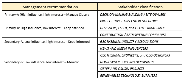
The stakeholders in a building retrofit project often are unfamiliar with shallow geothermal energy (SGE) technology and potentially have conflicting requirements [MUSE, 2019]. The following table shows the influence and interest of (in)directly involved stakeholders of typical SGE for building retrofit projects, in the framework of suggested management principles.
Table 1. Preliminary GEOFIT stakeholder matrix
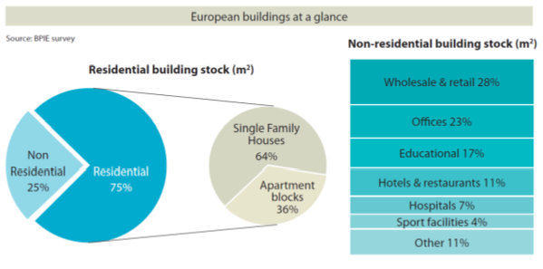
Building upon results of ‘sister projects’ such as the aforementioned MUSE, as well as GEO4CIVHIC and GRETA among others, GEOFIT takes a close look at the wide spectrum of SGE stakeholders in order to develop commercial-ready solutions. In order to gage SGE for building retrofit viability in Europe from a commercial standpoint, the typology of existing building stock is a critical factor. Therefore, one of the key images for this purpose comes from the Buildings Performance Institute Europe [1], shown below:
European Buildings at a glance
Another focus of GEOFIT Market Analysis is the sizing of market opportunities, defined by the specific technologies or ‘markets’ that together make up the full GEOFIT solution set. Initially investigated ‘markets’ include ground source heat pumps, heat exchangers, structural health monitoring, geographic information systems, building information modelling, building energy management systems, architecture, engineering, and construction, horizontal directional drilling, project management software and services, heating, ventilation, and air-conditioning, and drones.
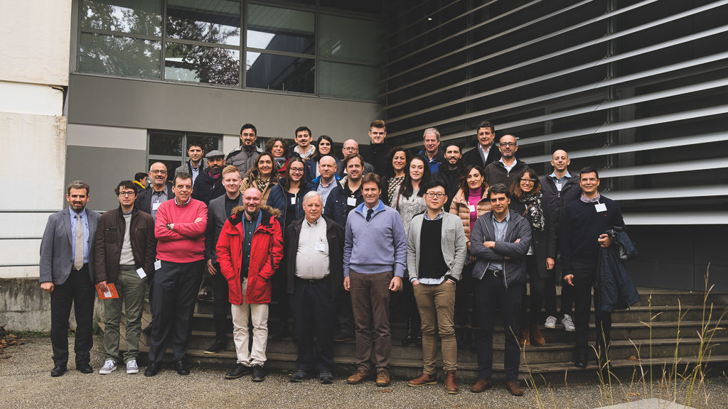
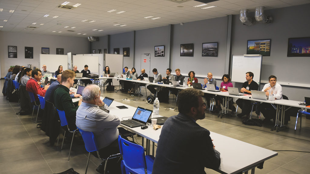
Bienvenue a Bordeaux! The most elegant city in France! Last week we were at the Geofit4th General Assembly where we had the chance to share all the advances achieved since the last meeting.
We managed to get into intense planning and discussing agenda, mostly related to very important issues regarding the implementation of the pilots and how the technical solutions and legal issues could be approached.
We found out, for example, of an interesting opportunity involving the different types of soils in the five different pilot sites. Drilling on different soils are options that can be explored and harnessed for the project interests.
The assembly also dealt with technical issues that will affect the activities scheduled for the next six months.
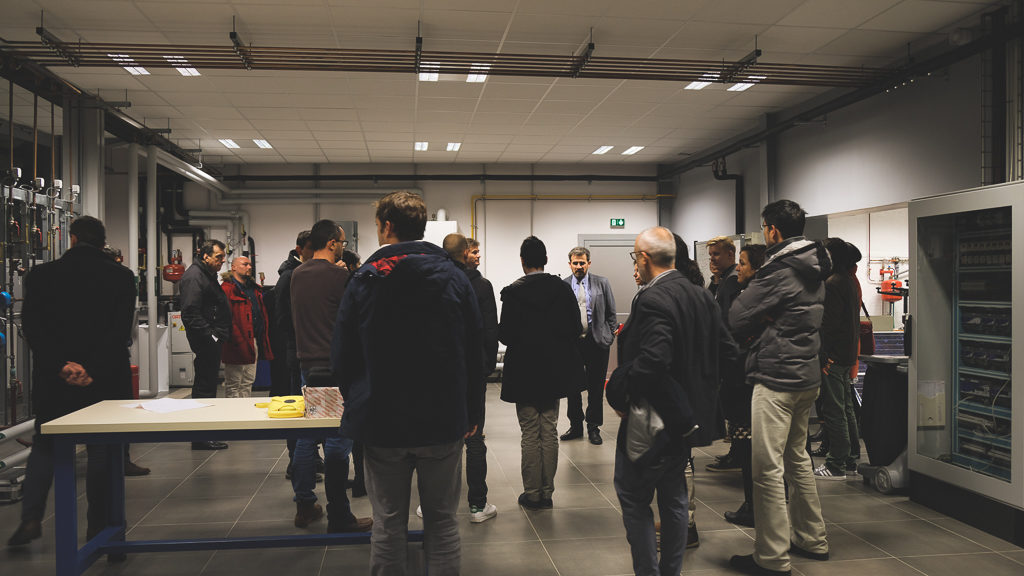
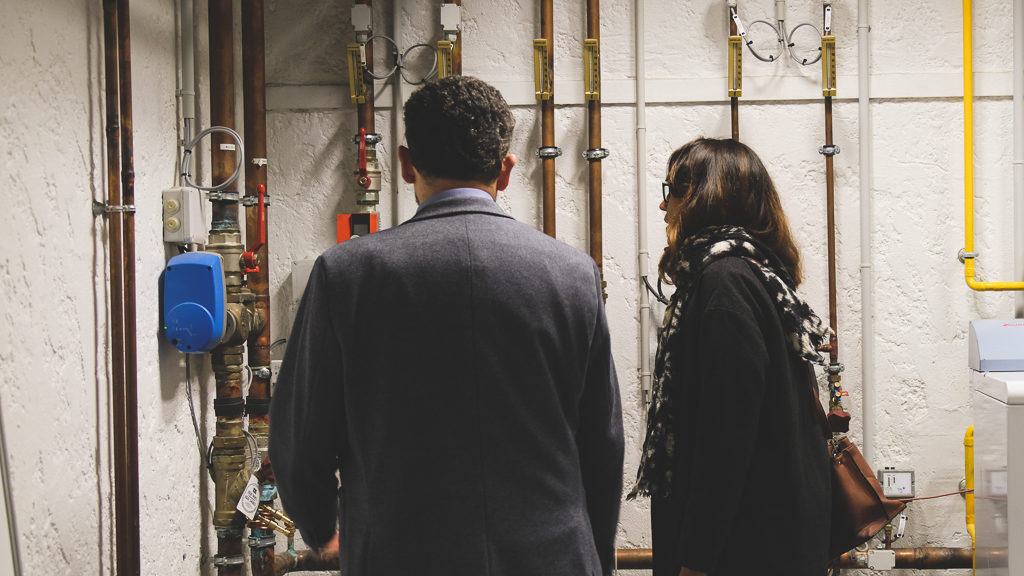
We also visited the demo site in Talence, in the very same building where we carried out the meeting. Our host (SAED) kindly showed the space where the future Geofit installation will be placed. It was almost as being on a living lab! Technical discussions and problem solving for the heat pump installation were part of the second day too.
The weather wasn’t very inspiring but we managed to get a very clear path for the next six months and everyone left with a positive feeling facing the new work roadmap. Merci la France!
Article by Henrikki Pieskä (KTH) and Qian Wang (Uponor)
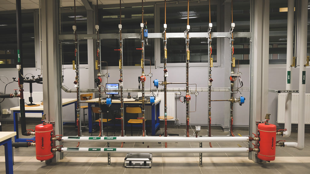
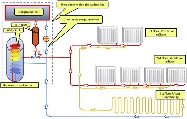
A heat emission system is an integral part of a building’s HVAC-system. Heat emission system is the interface between the heat source and the building user, so a proper design is essential both for energy efficiency and user comfort.
Example of a low temperature heating system combined with a heat pump (Hesaraki and Holmberg, 2014)
The objective of studying heat emission systems in GEOFIT is to present designs for innovative low temperature heating (LTH) and high temperature cooling (HTC) systems for the studied pilot buildings. There are many types of LTH and HTC systems, but common to all of them is that in comparison with conventional heat emission systems they require smaller temperature difference between the heat source and the conditioned space to operate the system.
LTH and HTC have therefore potential for increasing the efficiency of ground source heat pumps, because the smaller temperature difference means the heat pump has to do less work to cover that difference. In temperate climates it is in some cases even possible to use passive cooling, where a HTC system is directly coupled with a ground heat exchanger, thus bypassing the heat pump completely.
Geothermal based building retrofitting involve complex operations, such as drilling and digging, which must be considered as risky activities both for the excavation crews and the buildings close to the work area; managing these risks is one of the key objectives for GEOFIT.
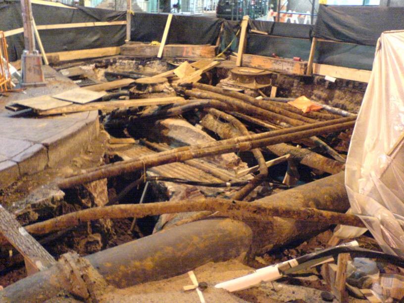
In fact, digging up an area without having reliable information on existing utilities and the local geology, can be problematic, even dangerous. For example, it’s worth noting that, in Europe, during new installations, about 90,000 incidences of third party damage to gas pipelines are reported every year and 100,000 in USA. There is little doubt that these instances of damage would be reduced by the use of reliable location techniques.
A typical tangle of buried assets
In this respect, the Ground Penetrating Radar (GPR) technique is very attractive because, amongst the various state-of-the-art methods available, it is the only one capable of accurately locating both metallic and non-metallic buried objects, without prior knowledge of their position.
Historically, the location of underground plant and equipment has been based on record information held by utility companies. This information, even if it exists (and much of it does not) is often inaccurate, incomplete or out of date.
Radar is well-known for its ability to detect aircraft, ships, vehicles, birds, rainstorms and other above-ground objects. It relies for its operation on the transmission of electro-magnetic energy, usually in the form of a pulse, and the detection of the small amount of energy that is reflected from the target. The round-trip transit time of the pulse and its reflection provide range information on the target.
Buried objects can also be detected by ground penetrating radar (GPR) and there are details of such work dating back to 1910, with the first pulsed experiments reported in 1926 when the depths of rock strata were determined by time-of-flight methods. The technique has since been used extensively in geophysical and geological investigation with the emphasis usually on deep penetration. Deep penetration requires operation at frequencies of a few MHz or tens of MHz, requiring large antennas and the accompanying consequence of low resolution of the objects detected.
The detection of buried utilities’ plant imposes a particular set of constraints on the effective use of a GPR. The majority of buried plant is within 1.5m of the ground surface, but it may have a wide variation in its size, may be metallic or non-metallic, may be in close proximity to other plant and may be buried in a wide range of soil types with implications for large differences in both the absorption and the velocity of propagation of electro-magnetic waves.
Rapid GPR data collection (IDS GeoRadar Stream C system)
In addition, a further limitation of the technique concerns the interpretation of GPR data, which is not trivial in many situations; in this respect, the latest developments in GPR are oriented towards the design of equipment featuring real-time 3D high resolution images of surveyed areas.
However, this visualisation improvement cannot fully solve that limitation; for this reason, in GEOFIT workpackage 2 novel and effective automatic processing tools will be developed. These tools are intended to aid operators to analyse the large amounts of information (tens of Gigabytes) as quickly and efficiently as possible, so that an exhaustive collection of underground information will be possible.
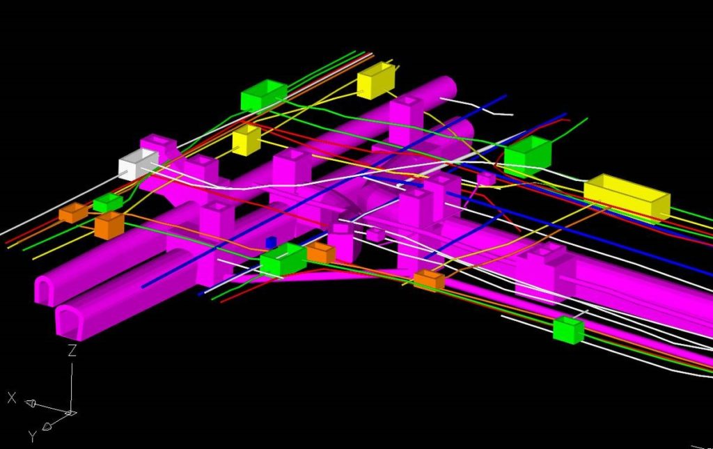
3D presentation of buried assets in a CAD.
Moreover, drilling and digging may in principle interfere with the stability of buildings close to the work area; as a matter of fact, ground in the vicinity of the buildings under renovation may be subjected to movement or even collapse when drilling/digging and this can compromise the stability of that building.
The solution being implemented in GEOFIT is based on the GBInSAR (Ground Based Interferometric Synthetic Aperture Radar) technology. GBInSAR equipment are nowadays used to remotely monitoring millimetre displacements at large distance (up to several kilometres). Typical applications concern the slope stability monitoring in mining plants, landslide monitoring in risk areas close to civil buildings, bridge load testing and stability monitoring.
Unfortunately, available technology use signals with a main frequency around 16 GHz and this does not permit to achieve a very high resolution and neither to measure the displacement of the building in 3-D.
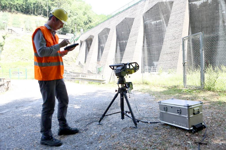
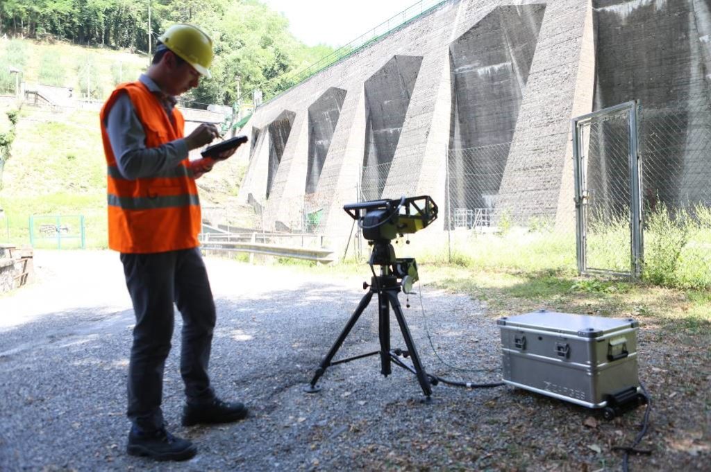
Monitoring a dam with a high definition GBInSAR
IDS GeoRadar has recently designed a radar that uses a millimeter wave technology (W band) and this is theoretically able to provide both range and angular measurements with a very high accuracy (< 0.1 millimiters). This technology is therefore candidate for being exploited in the monitoring the stability of a building in 3-D.
In this sense, in some pilot sites of GEOFIT a real-time stability monitoring session will be executed with the radar installed in the area interested by the retrofitting process. The system will therefore provide real-time information about the displacement of the building surface and warn the operators if a displacement of the buildings is measured.
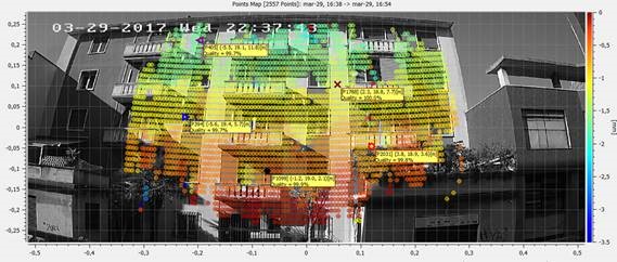
Possible output during building monitoring, the measured displacement is visualized as heat map
GEOFIT project represents a challenge and an opportunity for a geothermal based retrofitting of existing buildings. It covers several disciplines in terms of the processes developed and the data provisions at architectural, physical, geographical, technological, contractual, economical and life cycle levels.
In general terms, physical and energetic assessment is required to start a correlated retrofitting strategy aimed to improve the energy efficiency of an existing building. At the same time, the participation of different actors and disciplines are based on technical appreciations and judgements following a segmented timeline which provides a planning strategy to be considered complex in terms of the diversity involved. The strategy must be quite clear because different actors are playing to get the objectives from different expert disciplines and an integrative standardized methodology must be implemented because the sources of information are also diverse.
Expert disciplines:
Architecture
Geology
Geothermal analysis
Drilling
GIS
Heat exchange
HVAC
Mechanical, electrical and piping
Heat distribution
Control and monitoring
Economical
Contractual/legal
Construction/installation
Commissioning
Information sources:
Building owner
Geographical data provider
Geological data provider including drilling information (boreholes)
Geothermal systems design
Geothermal heat exchange design
Energy analysis, simulations and optimization (building)
Heat exchange and distribution design
Regulatory framework and permits
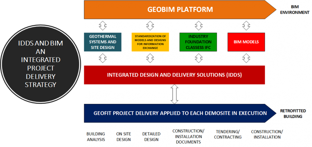
These two paths have been integrated with a common Integrated Design and Delivery Solution methodology (IDDS) that has made possible to define the BIM execution plan. The execution plan brings together actors and disciplines and states the information exchange requirements aimed to facilitate the integration within a GEOBIM platform by using open standards and Industrial Foundation Classes (IFC-4).
Onsite execution, delivery solutions and GEOBIM environment for GEOFIT project
GEOBIM concept is an integrated environment where architect (defined in terms of BIM -Building Information Modelling) and geographical information covering the geothermal conditions of the building site, come together. It is expected that BIM data coming from different CAD formats and translated into IFC-4 can be reused in geographical applications – BIM to GIS solutions. This is another challenge to be solved by GEOFIT project because there are many differences between BIM and Geo data formats. With respect to geographical information, CityGML and LandInfraGML are the most common standards and BIM is defined in IFC format within GEOFIT project. The main outcome is two geometrically model of identical objects, adding attributes (metadata) and level of detail to the objects in both development environments and use compatible open standards.
GEOBIM concept is an integrated environment where architect (defined in terms of BIM -Building Information Modelling) and geographical information covering the geothermal conditions of the building site, come together. It is expected that BIM data coming from different CAD formats and translated into IFC-4 can be reused in geographical applications – BIM to GIS solutions.
GEOBIM integration has been thought as a solution for the GEOFIT demo sites management covering the multidimensional concept of BIM, nevertheless, to import BIM data into geographical information systems is not a trivial task. The seven dimensions are: Geographical location, vector information (planes, drawings and available documentation), three-dimensional rendering of the buildings, duration and timing analysis – scheduling, cost analysis, sustainability assessment, lifecycle, and facility management and control beyond building occupancy. IDP supports the GEOFIT partnership to create this integrated environment providing a right decision making tool among all of the potential solutions along the geothermal facility lifespan of the project.
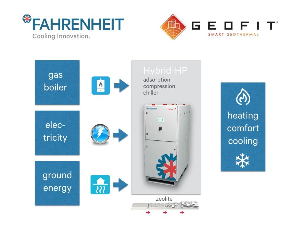
In the field of adsorption heat pumps, there are currently few studies on the combination with compression heat pumps and gas condensing boilers. Compared to conventional compression heat pumps, this concept offers a better EER and COP and makes it possible to use the optimum ratio between electrical and thermal energy depending on the operating conditions.
Part of the Geofit project is therefore the new development of a ground source hybrid heat pump consisting of a zeolite-based adsorption unit, driven by a gas condensing boiler, and an electrically driven compression unit. In this way, the electrical energy consumption of the heat pump is reduced and the system is able to work with less environmental energy, which also allows the realisation with less powerful earth sources. Due to the desired modular design, the concept will later be flexible and suitable for new installations, but also for retrofitting applications.
The heat pump developed by Fahrenheit GmbH will be tested in the laboratory of CNR ITAE under various boundary conditions and optimised for control before validation under real conditions in the demonstration buildings in Italy and France.
The focus of the development is on a simple connection of the gas condensing boiler and the ground collector to the hybrid heat pump and the optimisation of the control of the system.
Drilling is a key technology enabling heat exchangers installation and plays an important role in the building industry, both in sedimentary as well as in rock drilling. Tools employed in drilling are known as drill bits, and are the responsible for mechanically penetrating and crushing the rock underneath them. The wear of drilling tools has always been a predominant factor for the costs of geotechnical engineering measures and hard rock excavation. This fact is not only related to material and personnel costs arising from drill bit maintenance and replacement but also because of the direct and negative impact of wear on the drilling performance of a worn drill bit. Improper selection of a bit results in lower penetration rates, fast wearing of the teeth and frequent bit changes, which results in higher drilling costs overall.
Drilling is a key technology enabling heat exchangers installation and plays an important role in the building industry… Improper selection of a bit results in lower penetration rates, fast wearing of the teeth and frequent bit changes, which results in higher drilling costs overall.
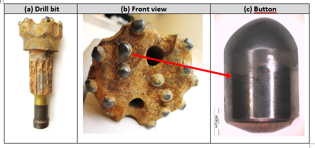
During the first year of GEOFIT project representative tools from vertical and horizontal drilling operations (needed in the different pilots of the project) have been selected and provided by CDP after their end life. For vertical drilling, down to the hole hammer and drag bits have been studied. For horizontal drilling, tricones (crushers) have been selected. Drill bit materials and main damaging mechanisms have been characterized and identified in Eurecat aiming to select alternative materials and solutions in order to:
reduce drilling times
improve rate of penetration (ROP)
improve abrasion and chipping/spalling resistance of drill bits
Figure 1. Analysed drill bit.
Drill bit inserts are commonly made with cemented carbides (also named hardmetal, cermets or cemented carbides), which are sintered composite materials consisting of two phases called hard phase (WC) and binder phase (Co). This combination of hardness and toughness makes WC-Co a successful material in drill bit inserts. However, the mechanical properties of the material are strongly dependent on composition and structure. A high Co content gives a tough material and high WC content gives a hard but brittle material. In addition, WC grain size and carbon content affect the properties.
Cemented carbide buttons are inserted and/or soldered into holes of a steel tool body. Taking into account the main damage mechanisms identified in hard metal buttons of drill bits for GEOFIT project and looking into recent publications and developments, advanced alternative hard metal grades have been selected to improve their tribo-mechanical properties based on (i) varying the grain size of the hard phase and the binder content, named Dual properties (DP) and (ii) macro gradients of Co-migration. In the same manner alternative steels with high strength, high wear resistance, good toughness and good dimension stability specially designed for drilling applications have been selected. These alternative hard metal and steel grades are being systematically tested in Eurecat laboratory in order to obtain a classification of their tribological behavior (friction and wear resistance).
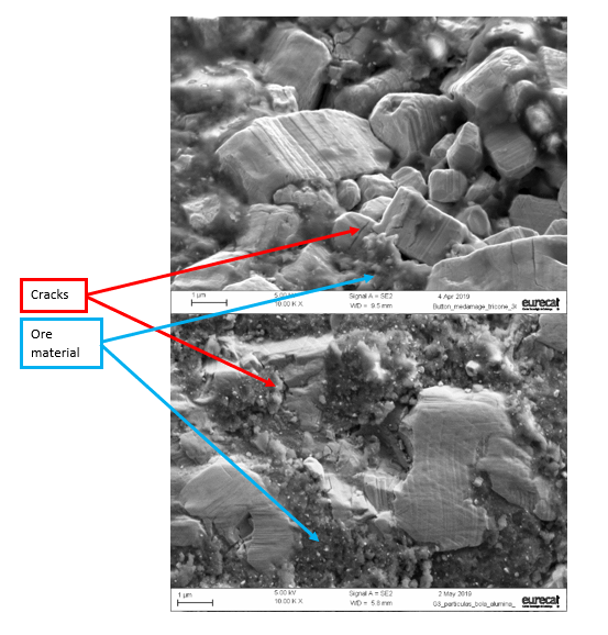
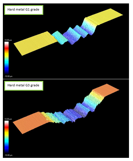
Wear tests have been designed in order to reproduce the same damaging mechanisms observed in drilling tools. Cemented carbide discs are slid against quartz and other abrasives used as counter parts. Quartz content of rock is one of the main geomechanical parameters influencing wear of drill bits. Test conditions (pressure, speed and time) have been adjusted until the same wear mechanisms have been obtained. Figure 2 compares surface of drill bit button from a tool and of a wear scar obtained in the lab, in both cases surface cracks, carbides deformation and adhesion of ore material are identified.
Figure 2. Scanning electron microscopy images (10,000 X magnification) of surfaces from a) worn drill bit button and b) wear scar from laboratory test.
Taking into account the main damage mechanisms identified in hard metal buttons of drill bits for GEOFIT project, advanced alternative hard metal and alternative steels grades have been selected to improve their tribo-mechanical properties and are being systematically tested in Eurecat laboratory in order to obtain a classification of their tribological behavior (friction and wear resistance).
Main results obtained in laboratory wear tests are:
Coefficient of friction: describes the interaction between drill bit material and rock material.
Wear rate: which is the worn drill bit material volume per sliding distance and applied force. Is obtained measuring wear scars (see Figure 3).
These are valuable parameters which are used to feed tool wear models that will predict tool live, models under development by LTU in the framework of GEOFIT project.
Figure 3. Wear scar topographic images corresponding to different grades of hard metal after wear tests under the same conditions (applied force, speed and time): G3 presents higher volume loss.
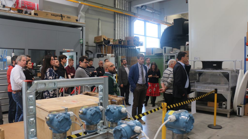
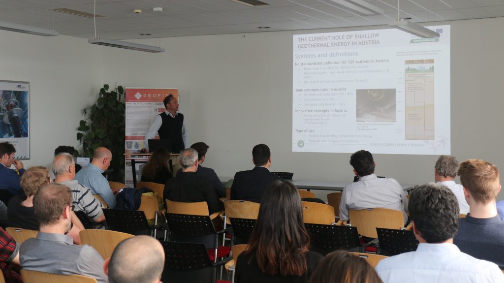
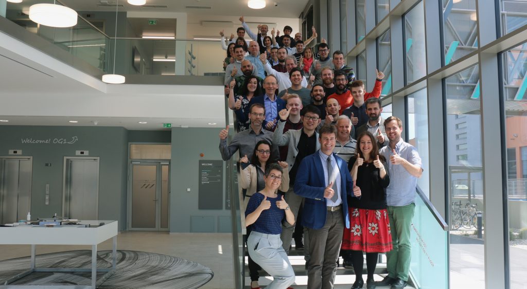
From the 7th to the 9th of May the GEOFIT consortium gathered in Vienna to hold their third general assembly. The meeting was organised by AIT (Austrian Institute of Technology) in their premises located in Giefinggasse, which also put together a traditional Austrian dinner in the city centre for all partners to enjoy the food and carry on discussing emerging ideas.
Significant progress were made regarding the core hardware technology to be installed on the pilot sites during this three-day meeting. Very important decisions were made on the coordination of work packages.
Highlights included the management of data gathering and analyses from the pilots’ hardware implementation, and reviewing the advances made regarding the advances on the overall system and building integration for efficient management.
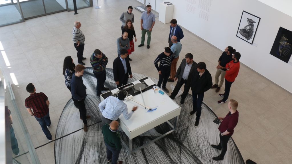
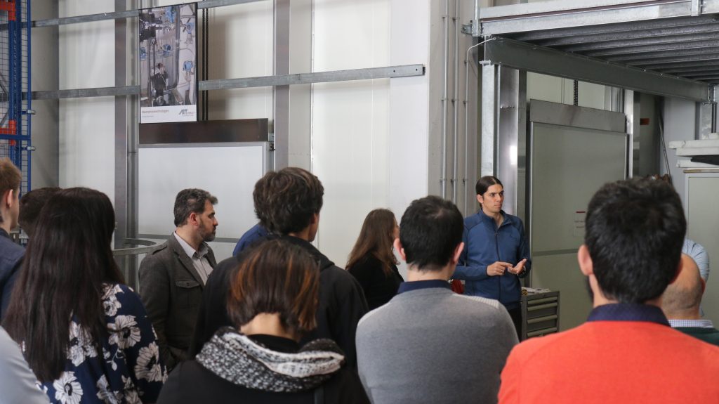
AIT also organised a visit to their impressive lab premises where all partners could see by themselves the prospective advances that can be reached in geothermal energy development. The building itself had implemented energy efficient tools that help reduce energy consumption.
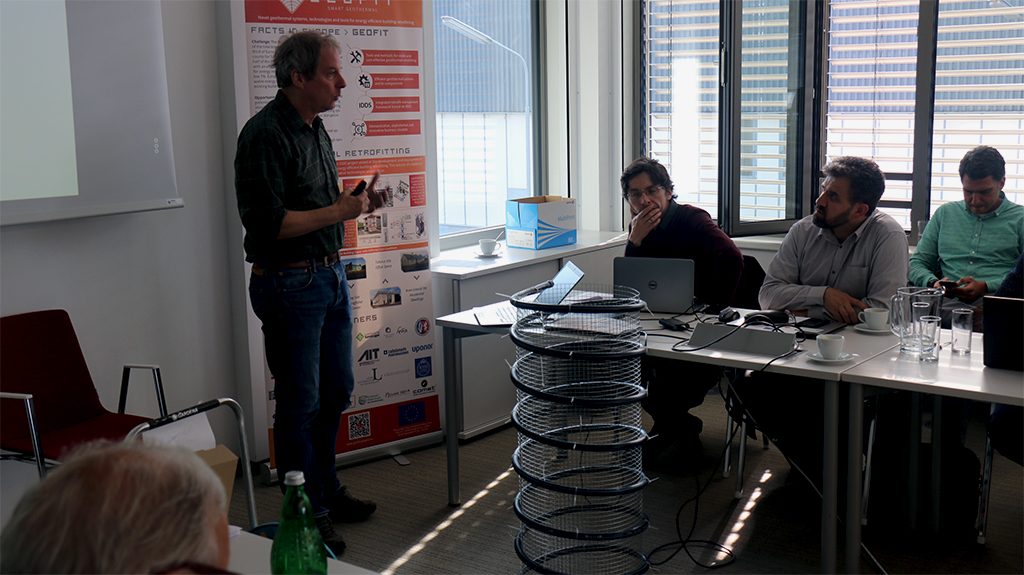
On top of the general assembly a very interesting stakeholder workshop was held on the 8th May with participation from AIT -that was also the organiser- GROEN, CDP and Uponor were all partners participated.
The consortium closed the meetinghaving established clear goals for the next 6 months and looking forward to the work ahead.