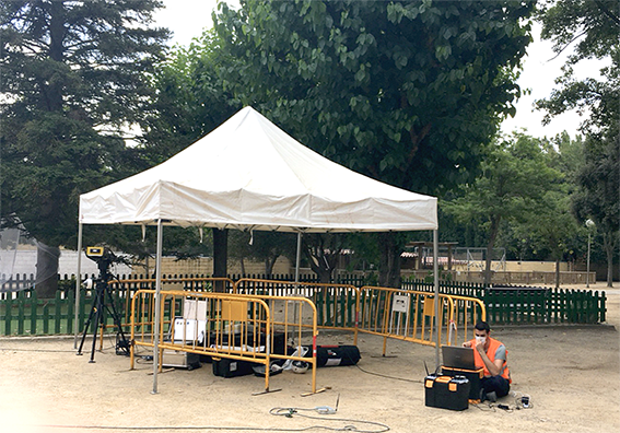
From 27th to 31st July, SIART and IDSGEORADAR were at Sant Cugat pilot for structural monitoring, during the same week drilling works started. The goal was to perform structural monitoring before and during drilling, and see any impact in the school buildings.
IDSGEORADAR installed a Hydra-G system which monitored real-time measurements of sub-millimetric displacements in the administrative building and in the primary school. This system provides the high-accuracy and resolution radar technology. The system was accompanied by an optical and infrared HD camera providing real- time visual inspection of monitored area, draping radar data on a 3D model of the scene created using the radar system.
On the other hand, SIART installed several accelerometers in both buildings, administrative and primary school, to monitor vibrations before and during the first drilling carried out on 31st July. The goal of monitoring before drilling works is to know the building frequency, and see, once the drilling starts, if it has changed due to the vibrations propagation throughout the terrain. Once data has been captured, SIART will analyze them and present some results.
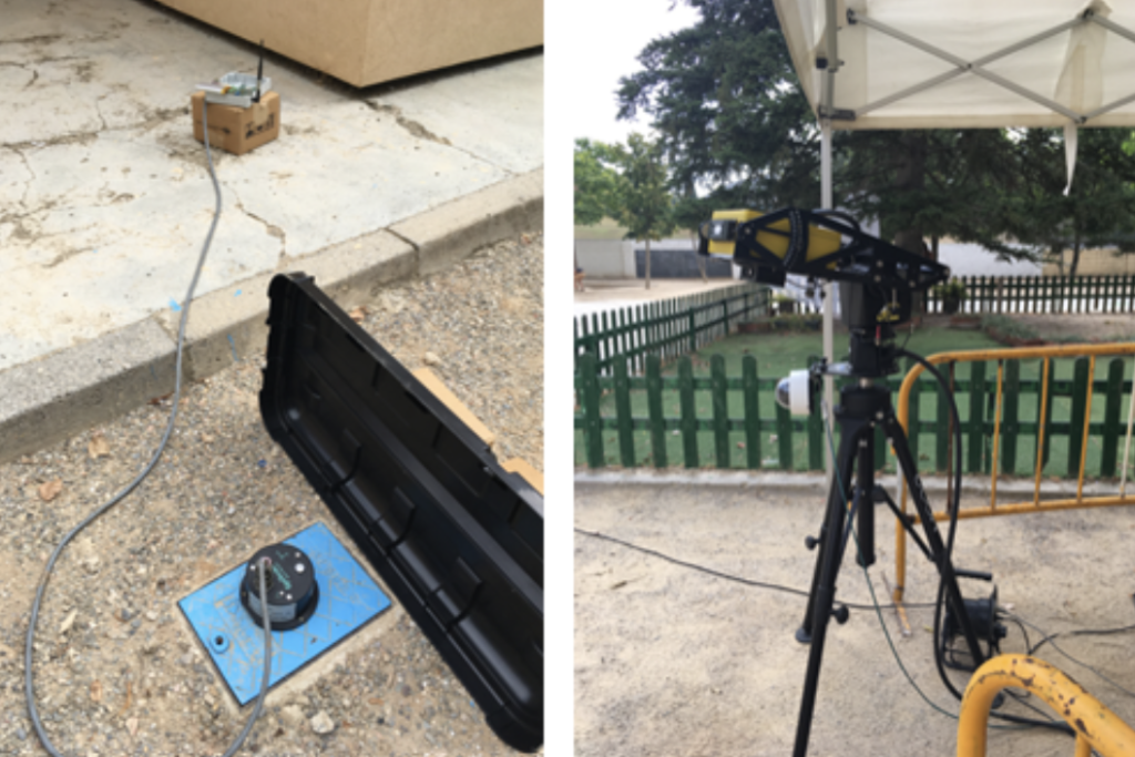
On the left: one of the accelerometers installed by SIART; On the right: Hydra-G system and camera installed by IDSGEORADAR.
Geothermal based building retrofitting involve complex operations, such as drilling and digging, which must be considered as risky activities both for the excavation crews and the buildings close to the work area; managing these risks is one of the key objectives for GEOFIT.
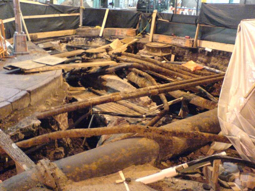
In fact, digging up an area without having reliable information on existing utilities and the local geology, can be problematic, even dangerous. For example, it’s worth noting that, in Europe, during new installations, about 90,000 incidences of third party damage to gas pipelines are reported every year and 100,000 in USA. There is little doubt that these instances of damage would be reduced by the use of reliable location techniques.
A typical tangle of buried assets
In this respect, the Ground Penetrating Radar (GPR) technique is very attractive because, amongst the various state-of-the-art methods available, it is the only one capable of accurately locating both metallic and non-metallic buried objects, without prior knowledge of their position.
Historically, the location of underground plant and equipment has been based on record information held by utility companies. This information, even if it exists (and much of it does not) is often inaccurate, incomplete or out of date.
Radar is well-known for its ability to detect aircraft, ships, vehicles, birds, rainstorms and other above-ground objects. It relies for its operation on the transmission of electro-magnetic energy, usually in the form of a pulse, and the detection of the small amount of energy that is reflected from the target. The round-trip transit time of the pulse and its reflection provide range information on the target.
Buried objects can also be detected by ground penetrating radar (GPR) and there are details of such work dating back to 1910, with the first pulsed experiments reported in 1926 when the depths of rock strata were determined by time-of-flight methods. The technique has since been used extensively in geophysical and geological investigation with the emphasis usually on deep penetration. Deep penetration requires operation at frequencies of a few MHz or tens of MHz, requiring large antennas and the accompanying consequence of low resolution of the objects detected.
The detection of buried utilities’ plant imposes a particular set of constraints on the effective use of a GPR. The majority of buried plant is within 1.5m of the ground surface, but it may have a wide variation in its size, may be metallic or non-metallic, may be in close proximity to other plant and may be buried in a wide range of soil types with implications for large differences in both the absorption and the velocity of propagation of electro-magnetic waves.
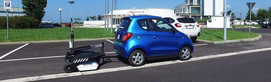
Rapid GPR data collection (IDS GeoRadar Stream C system)
In addition, a further limitation of the technique concerns the interpretation of GPR data, which is not trivial in many situations; in this respect, the latest developments in GPR are oriented towards the design of equipment featuring real-time 3D high resolution images of surveyed areas.
However, this visualisation improvement cannot fully solve that limitation; for this reason, in GEOFIT workpackage 2 novel and effective automatic processing tools will be developed. These tools are intended to aid operators to analyse the large amounts of information (tens of Gigabytes) as quickly and efficiently as possible, so that an exhaustive collection of underground information will be possible.
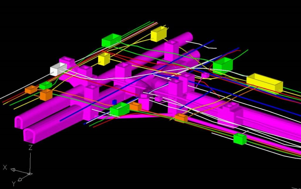
3D presentation of buried assets in a CAD.
Moreover, drilling and digging may in principle interfere with the stability of buildings close to the work area; as a matter of fact, ground in the vicinity of the buildings under renovation may be subjected to movement or even collapse when drilling/digging and this can compromise the stability of that building.
The solution being implemented in GEOFIT is based on the GBInSAR (Ground Based Interferometric Synthetic Aperture Radar) technology. GBInSAR equipment are nowadays used to remotely monitoring millimetre displacements at large distance (up to several kilometres). Typical applications concern the slope stability monitoring in mining plants, landslide monitoring in risk areas close to civil buildings, bridge load testing and stability monitoring.
Unfortunately, available technology use signals with a main frequency around 16 GHz and this does not permit to achieve a very high resolution and neither to measure the displacement of the building in 3-D.
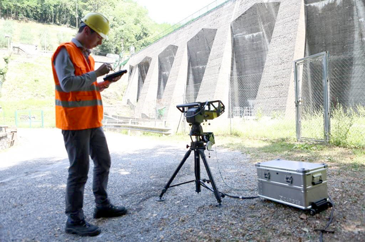
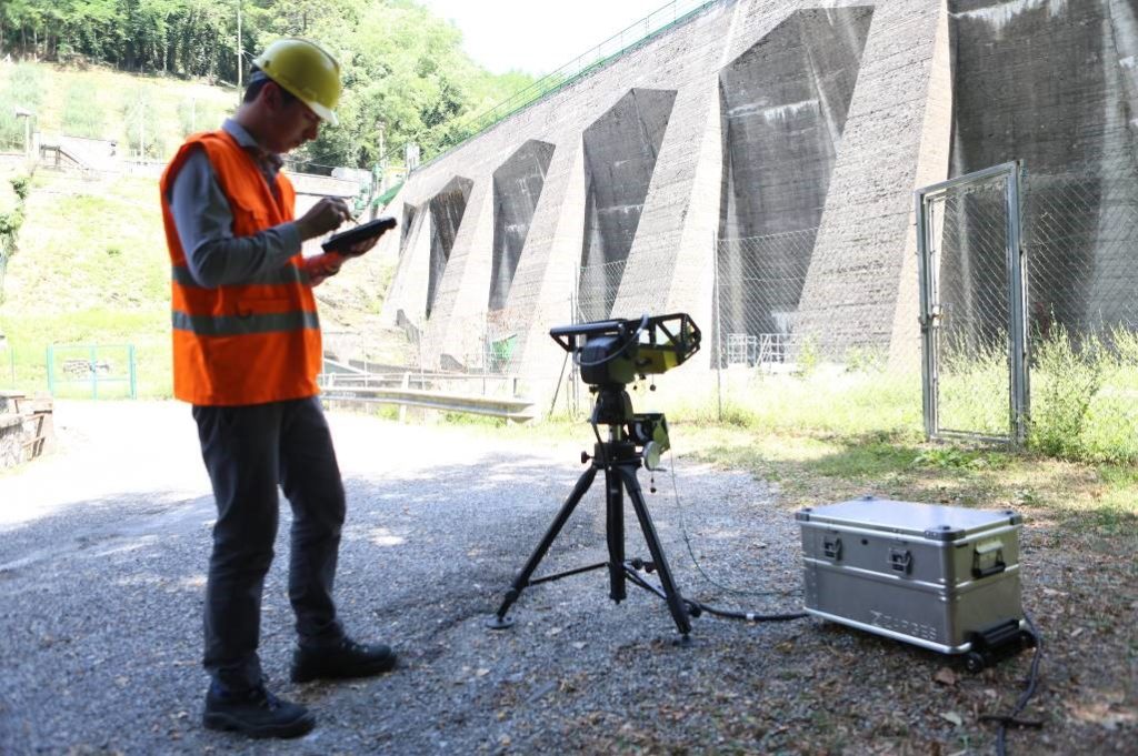
Monitoring a dam with a high definition GBInSAR
IDS GeoRadar has recently designed a radar that uses a millimeter wave technology (W band) and this is theoretically able to provide both range and angular measurements with a very high accuracy (< 0.1 millimiters). This technology is therefore candidate for being exploited in the monitoring the stability of a building in 3-D.
In this sense, in some pilot sites of GEOFIT a real-time stability monitoring session will be executed with the radar installed in the area interested by the retrofitting process. The system will therefore provide real-time information about the displacement of the building surface and warn the operators if a displacement of the buildings is measured.
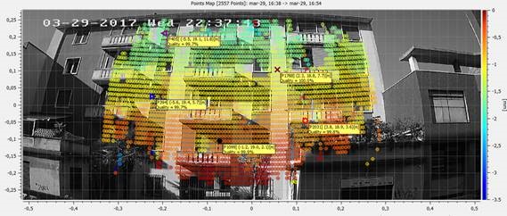
Possible output during building monitoring, the measured displacement is visualized as heat map
Drilling is a key technology enabling heat exchangers installation and plays an important role in the building industry, both in sedimentary as well as in rock drilling. Tools employed in drilling are known as drill bits, and are the responsible for mechanically penetrating and crushing the rock underneath them. The wear of drilling tools has always been a predominant factor for the costs of geotechnical engineering measures and hard rock excavation. This fact is not only related to material and personnel costs arising from drill bit maintenance and replacement but also because of the direct and negative impact of wear on the drilling performance of a worn drill bit. Improper selection of a bit results in lower penetration rates, fast wearing of the teeth and frequent bit changes, which results in higher drilling costs overall.
Drilling is a key technology enabling heat exchangers installation and plays an important role in the building industry… Improper selection of a bit results in lower penetration rates, fast wearing of the teeth and frequent bit changes, which results in higher drilling costs overall.
During the first year of GEOFIT project representative tools from vertical and horizontal drilling operations (needed in the different pilots of the project) have been selected and provided by CDP after their end life. For vertical drilling, down to the hole hammer and drag bits have been studied. For horizontal drilling, tricones (crushers) have been selected. Drill bit materials and main damaging mechanisms have been characterized and identified in Eurecat aiming to select alternative materials and solutions in order to:
reduce drilling times
improve rate of penetration (ROP)
improve abrasion and chipping/spalling resistance of drill bits
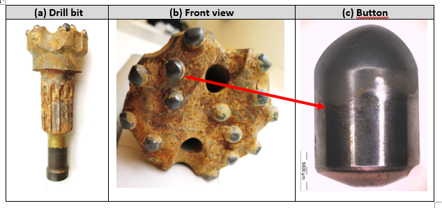
Figure 1. Analysed drill bit.
Drill bit inserts are commonly made with cemented carbides (also named hardmetal, cermets or cemented carbides), which are sintered composite materials consisting of two phases called hard phase (WC) and binder phase (Co). This combination of hardness and toughness makes WC-Co a successful material in drill bit inserts. However, the mechanical properties of the material are strongly dependent on composition and structure. A high Co content gives a tough material and high WC content gives a hard but brittle material. In addition, WC grain size and carbon content affect the properties.
Cemented carbide buttons are inserted and/or soldered into holes of a steel tool body. Taking into account the main damage mechanisms identified in hard metal buttons of drill bits for GEOFIT project and looking into recent publications and developments, advanced alternative hard metal grades have been selected to improve their tribo-mechanical properties based on (i) varying the grain size of the hard phase and the binder content, named Dual properties (DP) and (ii) macro gradients of Co-migration. In the same manner alternative steels with high strength, high wear resistance, good toughness and good dimension stability specially designed for drilling applications have been selected. These alternative hard metal and steel grades are being systematically tested in Eurecat laboratory in order to obtain a classification of their tribological behavior (friction and wear resistance).
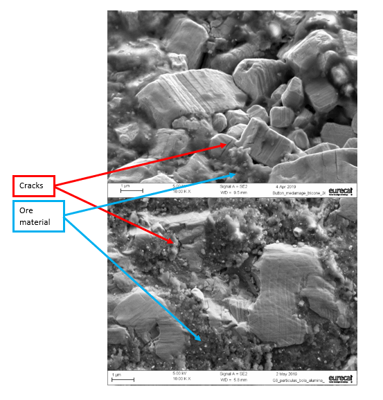
Wear tests have been designed in order to reproduce the same damaging mechanisms observed in drilling tools. Cemented carbide discs are slid against quartz and other abrasives used as counter parts. Quartz content of rock is one of the main geomechanical parameters influencing wear of drill bits. Test conditions (pressure, speed and time) have been adjusted until the same wear mechanisms have been obtained. Figure 2 compares surface of drill bit button from a tool and of a wear scar obtained in the lab, in both cases surface cracks, carbides deformation and adhesion of ore material are identified.
Figure 2. Scanning electron microscopy images (10,000 X magnification) of surfaces from a) worn drill bit button and b) wear scar from laboratory test.
Taking into account the main damage mechanisms identified in hard metal buttons of drill bits for GEOFIT project, advanced alternative hard metal and alternative steels grades have been selected to improve their tribo-mechanical properties and are being systematically tested in Eurecat laboratory in order to obtain a classification of their tribological behavior (friction and wear resistance).
Main results obtained in laboratory wear tests are:
Coefficient of friction: describes the interaction between drill bit material and rock material.
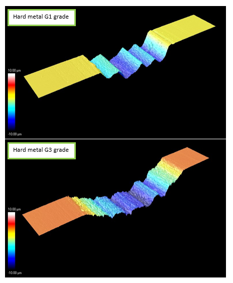
Wear rate: which is the worn drill bit material volume per sliding distance and applied force. Is obtained measuring wear scars (see Figure 3).
These are valuable parameters which are used to feed tool wear models that will predict tool live, models under development by LTU in the framework of GEOFIT project.
Figure 3. Wear scar topographic images corresponding to different grades of hard metal after wear tests under the same conditions (applied force, speed and time): G3 presents higher volume loss.
(DRILLING WORKS – MODELLING AND VIRTUALIZATION – GEOTHERMAL BIM INTEGRATION VISUALIZATION, MONITORING AND LIFE CYCLE CONTROL)
Deliverable by IDP
GEOFIT project creates the perfect interaction environment bringing together a set of different disciplines, technologies, knowledge and innovation. One of the main achievements of the project is to create a seven-dimension BIM model covering different aspects like design, planning, programming, installation and deployment, monitoring, simulating, and life cycle and costs management of a building geothermal retrofitting project.