Model development and performance analysis of Novel Shallow Ground Heat Exchangers

by Henk Witte – Groenholland

One of the key aspects of the EU GEOFIT project is the development of integrated engineering design tools for different types of ground heat exchangers. This toolkit provides design methodologies for vertical borehole heat exchangers, shallow horizontal and slinky type heat exchangers, and earth basket (spiral) heat exchangers.

Ground heat exchangers (GHEX) are used to provide a heat source or heat sink used for heating or cooling a building. They are typically constructed of plastic pipes installed in different configurations in the ground. A fluid is circulated in the pipes and the GHEX extracts heat from the ground (heating operation) or rejects heat to the ground (cooling operation).

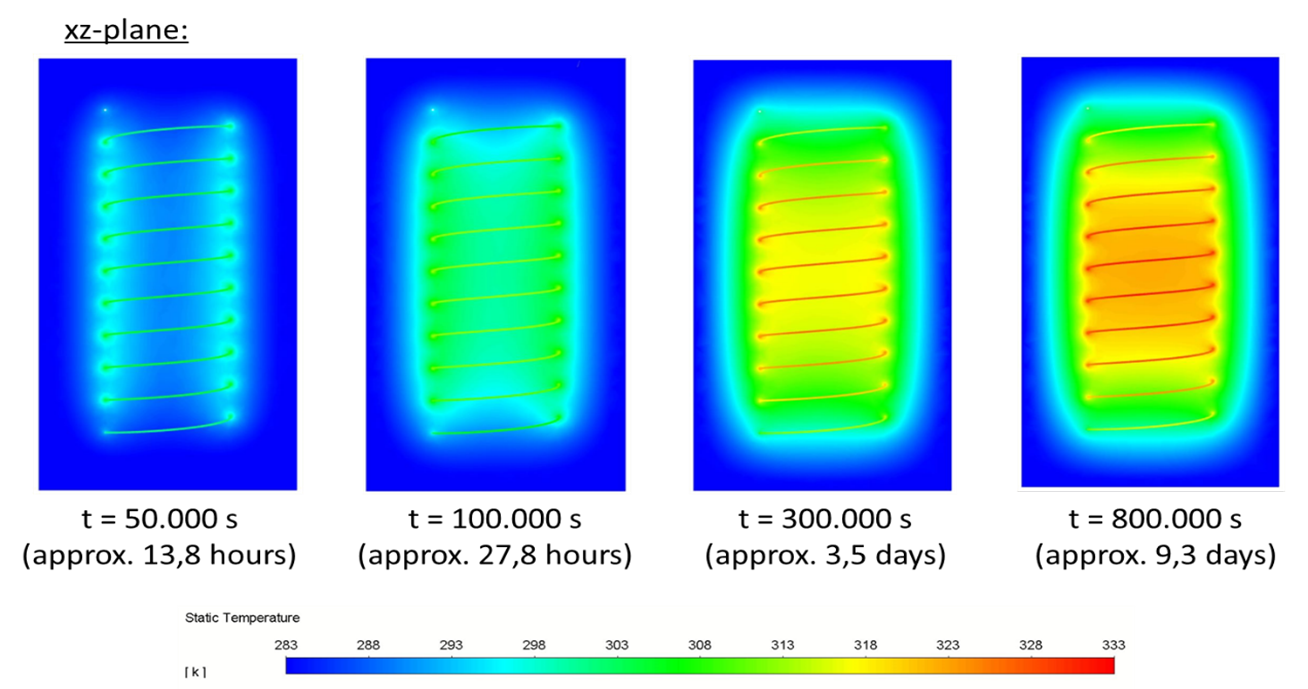
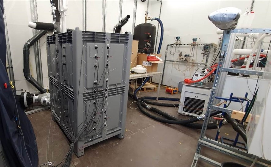
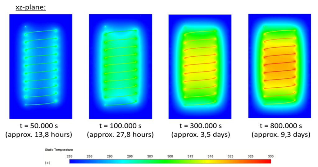
For the validation of the analytical solutions used in the integrated engineering design toolkit, especially the new finite line source solutions developed for earth basket (spiral) heat exchangers laboratory experiments (figure 1) and detailed numerical simulations (figure 2) have been performed.

Figure 1. Experimental sandbox setup for earth basket (spiral) heat exchanger characterisation (foto: AIT)

The performance of a ground heat exchanger can be summarized to two key parameters:

  1. Pressure drop: A measure of the pump energy needed to move the fluid through the heat exchanger.
  2. Thermal resistance between fluid and ground: A measure of the thermal performance of the GHEX.
Figure 2. CFD simulation of earth basket (spiral) heat exchanger (foto: AIT).

The goal of the performance analysis is to identify key-design parameters affecting the overall system performance. Parameters investigated include:

  • Diameter of the earth basket (spiral) heat exchanger
  • Pipe diameter in relation to flow rate and pressure drop
  • Distance between adjacent rings in relation to total length and buried depth
  • Soil thermal parameters

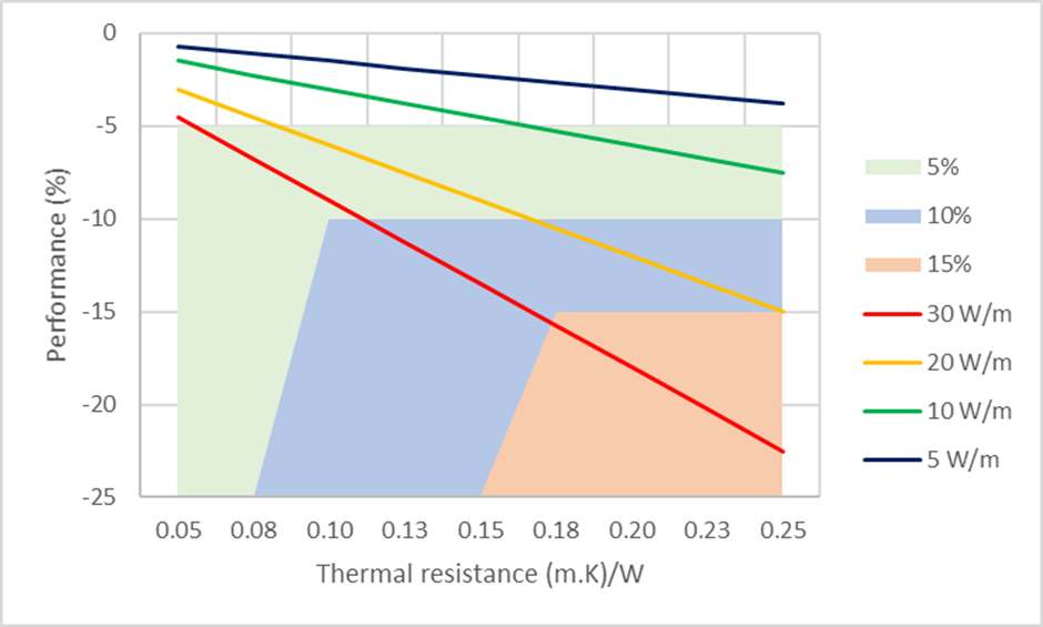
Evaluation of the results of the performance analysis should take into account the actual effect on system performance. As an example, it can be attempted to reduce the thermal resistance in all cases as much as possible. However, the effect on performance is related to the actual heat rate of the system (figure 3). It is clear that with a low heat rate (5 W/m) the thermal resistance can be allowed to be high without affecting performance. These results will have implications for operating these systems during part-load conditions, which is important in view of the application of frequency-controlled compressors in the heat pumps. In this way, the results of the GEOFIT project not only provide designers with the tools to evaluate different types of ground heat exchangers in one integrated tool but also allows optimization of actual system operational control.

Figure 3. Relation between thermal resistance (fluid to ground) and energy performance degradation for different specific heat rates.

REFERENCES

Meeng, C.L (2020). Development of an engineering tool for the design of novel shallow ground heat exchangers – GEOFIT. MSc Thesis TU Eindhoven.

Dörr, C.J. (2020). CFD Analysis of Ground Heat Exchangers. MSc Thesis Montan Universität Leoben, Austrian Institute of Technology.

Kling, S. (2020). Experimental characterization of Helix-Type Ground Source Heat Exchangers Configurations for Developing a Standardized Design Tool. MSc Thesis FH Burgenland University of Applied Sciences, Austrian Institute of Technology.

Drilling Bit Materials for an Improved Performance

by Montse Vilaseca, EURECAT

Drilling is a key technology enabling heat exchangers installation and plays an important role in the building industry, both in sedimentary as well as in rock drilling. Tools employed in drilling are known as drill bits, and are the responsible for mechanically penetrating and crushing the rock underneath them. The wear of drilling tools has always been a predominant factor for the costs of geotechnical engineering measures and hard rock excavation. This fact is not only related to material and personnel costs arising from drill bit maintenance and replacement but also because of the direct and negative impact of wear on the drilling performance of a worn drill bit. Improper selection of a bit results in lower penetration rates, fast wearing of the teeth and frequent bit changes, which results in higher drilling costs overall.

Drilling is a key technology enabling heat exchangers installation and plays an important role in the building industry… Improper selection of a bit results in lower penetration rates, fast wearing of the teeth and frequent bit changes, which results in higher drilling costs overall.

During the first year of GEOFIT project representative tools from vertical and horizontal drilling operations (needed in the different pilots of the project) have been selected and provided by CDP after their end life. For vertical drilling, down to the hole hammer and drag bits have been studied. For horizontal drilling, tricones (crushers) have been selected. Drill bit materials and main damaging mechanisms have been characterized and identified in Eurecat aiming to select alternative materials and solutions in order to:

    • reduce drilling times
    • improve rate of penetration (ROP)
    • improve abrasion and chipping/spalling resistance of drill bits


Figure 1. Analysed drill bit.


Drill bit inserts are commonly made with cemented carbides (also named hardmetal, cermets or cemented carbides), which are sintered composite materials consisting of two phases called hard phase (WC) and binder phase (Co). This combination of hardness and toughness makes WC-Co a successful material in drill bit inserts. However, the mechanical properties of the material are strongly dependent on composition and structure. A high Co content gives a tough material and high WC content gives a hard but brittle material. In addition, WC grain size and carbon content affect the properties.

Cemented carbide buttons are inserted and/or soldered into holes of a steel tool body. Taking into account the main damage mechanisms identified in hard metal buttons of drill bits for GEOFIT project and looking into recent publications and developments, advanced alternative hard metal grades have been selected to improve their tribo-mechanical properties based on (i) varying the grain size of the hard phase and the binder content, named Dual properties (DP) and (ii) macro gradients of Co-migration. In the same manner alternative steels with high strength, high wear resistance, good toughness and good dimension stability specially designed for drilling applications have been selected. These alternative hard metal and steel grades are being systematically tested in Eurecat laboratory in order to obtain a classification of their tribological behavior (friction and wear resistance).

Wear tests have been designed in order to reproduce the same damaging mechanisms observed in drilling tools. Cemented carbide discs are slid against quartz and other abrasives used as counter parts. Quartz content of rock is one of the main geomechanical parameters influencing wear of drill bits. Test conditions (pressure, speed and time) have been adjusted until the same wear mechanisms have been obtained. Figure 2 compares surface of drill bit button from a tool and of a wear scar obtained in the lab, in both cases surface cracks, carbides deformation and adhesion of ore material are identified.

Figure 2. Scanning electron microscopy images (10,000 X magnification) of surfaces from a) worn drill bit button and b) wear scar from laboratory test.


Taking into account the main damage mechanisms identified in hard metal buttons of drill bits for GEOFIT project, advanced alternative hard metal and alternative steels grades have been selected to improve their tribo-mechanical properties and are being systematically tested in Eurecat laboratory in order to obtain a classification of their tribological behavior (friction and wear resistance).

Main results obtained in laboratory wear tests are:

    • Coefficient of friction: describes the interaction between drill bit material and rock material.
    • Wear rate: which is the worn drill bit material volume per sliding distance and applied force. Is obtained measuring wear scars (see Figure 3).

These are valuable parameters which are used to feed tool wear models that will predict tool live, models under development by LTU in the framework of GEOFIT project.

Figure 3. Wear scar topographic images corresponding to different grades of hard metal after wear tests under the same conditions (applied force, speed and time): G3 presents higher volume loss.